Creating an assembly
Small basic glossary:
Single item: Any line of materials, labour and others that will display a quantity of itself in the grid. Also called "component".
Assembly: Grouping of simple items
Variables: Represents manually entered quantities and formula results required for the calculation of simple items (Area, linear feet etc...)
Management and Description of an Assembly
This is where the project-specific portion of the calculations are found, depending on the compositions, conditions, restrictions and other variables that result in costs.
The precise calculation details will generally be grouped into two types of assemblies.
Ass1 (Deliverable or Parent) Main Assembly gathers all the information to be provided to the specialized assemblies (Ass2 and others).
The name of the line represents a global composition (Exterior Wooden Wall)
This line will accumulate the results of the sub-assemblies under it.
The assembly groups the required sub-assemblies.
Ass2 (Operation or Child) Sub-assembly by specialized steps.
This line contains the required variables provided by Ass1 for its own calculation and distribution.
This line contains, if required, the variables for the calculation of the fixings. FixNnPi or FixNbPi2 as required and ALWAYS FixNbReq which will contain the calculation formula.
This line contains, if required, the variables for the calculation choice and ALWAYS Surf for the surfaces which will contain the value used for the calculation.
The assembly contains all the components of any kind (framing, gypsum, insulation ...) for the cost estimate related to its specialized title.
This line will cumulate the results of the items under it.
Before starting the creation of an assembly it is necessary to check:
That there will be no duplication, perform a search with different possible names to be sure that an existing assembly does not already fill the need.
Carefully determine the Classification Code according to the most intuitive specification section for the research and the assembly level according to the protocol.
Ex: 03A1 for a level 1 assembly in the Concrete section
Think about the best possible description of the assembly
Clear, precise, concise, easy to read, according to the protocol
Promote an intuitive and logical description for future use
Always include the Management Unit in () at the end of the description.
Creating an assembly :
Creation of the line: Click on the + button at the top left
In the window that opens,
Type: Select Assembly
Make sure the Catalog Item button is in bold
Classification code: According to the reflection made as mentioned above
Code: Nothing to do here, this number is unique and specific to this creation.
Name: According to the reflection made as mentioned above
Description: Indicate here additional details if needed, ex: included in this assembly.
Quantity, Management Qty: Indicate 1 unit
Press Create
Depending on the level required, certain steps are crucial to facilitate the next step.
For a level 1 assembly (Ass1)
Create or Integrate the Dimensions block and the required sub-assemblies see Dimension lines
Be careful to respect the following steps:
The use of A1 and A2 designations at the right steps.
Selecting the right type of parameter according to the type of assembly and the calculation need (linear, surface and/or volume)
Respect the order of all variable parameters according to the protocol
It is recommended to establish a classification logic of the parameters at the level of Ass1 and Dim1 to facilitate the links with the A2 sub-assemblies.
Principle of the Standard Codes
In level 1 assemblies (Deliverables) Assembly coding ex: 06A1
Coding of an assembly in carpentry 06 ex: Exterior Wooden Wall & A1 for a level 1 assembly
The parameters used must be sums of the collected values of lengths, surfaces and volumes from a dimension type assembly see dimension lines. These values are then communicated to level 2 assemblies (Operation).
Level 1 assemblies (Deliverables) must be duplicated in their entirety during the estimating process. They can then be adapted to conform to other wall types.
In level 2 assemblies (Operation), the values are connected to the values of the A1 assembly. The use of the level 2 assembly is the realization of an operation entering the composition of a deliverable. E.g. Supply and installation of gypsum e.g. 09A2.
Coding of an assembly supply and installation of gypsum: 09A2
The parameters used are private parameters: Long (Length) Surf (surface) & Vol (Volume)
Note: other specific parameters can be used ex Perim (Perimeter)
It is possible to insert operations at different stages in order to comply with different wall compositions.
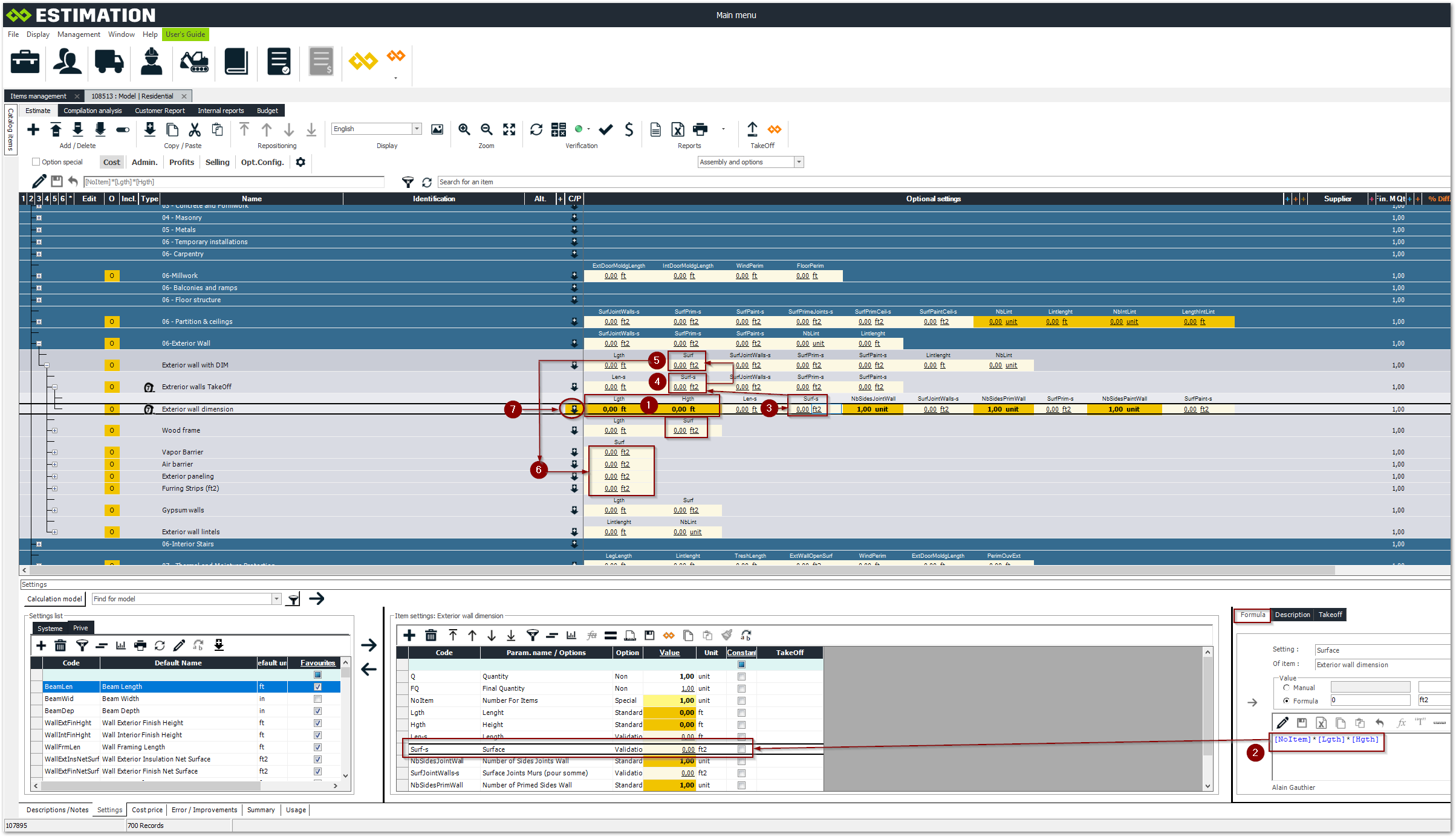
Example of assembly using the Universal Standard method

Enter length and height data
Formula for determining the area of a wall
The total is indicated in the parameter [Surf-s].
Total areas are compiled to be transferred to the top assembly: Exterior Wall with DIM
The result of the surface total is transferred to the line corresponding to assembly A1(Deliverable) for redistribution to assemblies
The compiled areas are transferred to the operations to determine the material and labour quantities for each operation (Ex.: A2 operation: Vapor barrier)
The dimension line can be duplicated to count other walls of the same composition.